Over the past few days, I've been working on the anti food stealing mechanism, along with the enclosure for the electronics (battery and fan).
anti food stealing mechanism
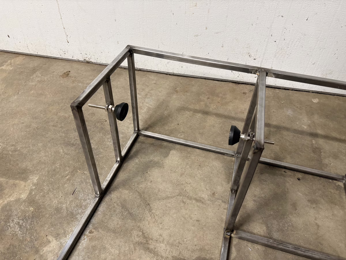
The mechanism to prevent food theft is pretty simple, it just clamps the feeder between two swivel leveling feet. The feet thread directly in to the frame, and will provide a small amount of clamping force to prevent the feeder from being rocked side to side. Since my square bar stock could not be located in my well organized metal scrap pile, I did what anyone would do - just welded two zinc'd nuts to the frame:
What is a tap?
These two will prevent side to side rocking, and the back of the frame will prevent front to back. The whole thing will be sitting up against a wall, preventing back to front motion.
We'll see how well this works. The fallback plan is to float and completely enclose the feeder, and have the output fall down a chute into a bowl that sits below the chute (as designed, a bowl snaps into the bottom of the feeder).
electronics enclosure + fan mount
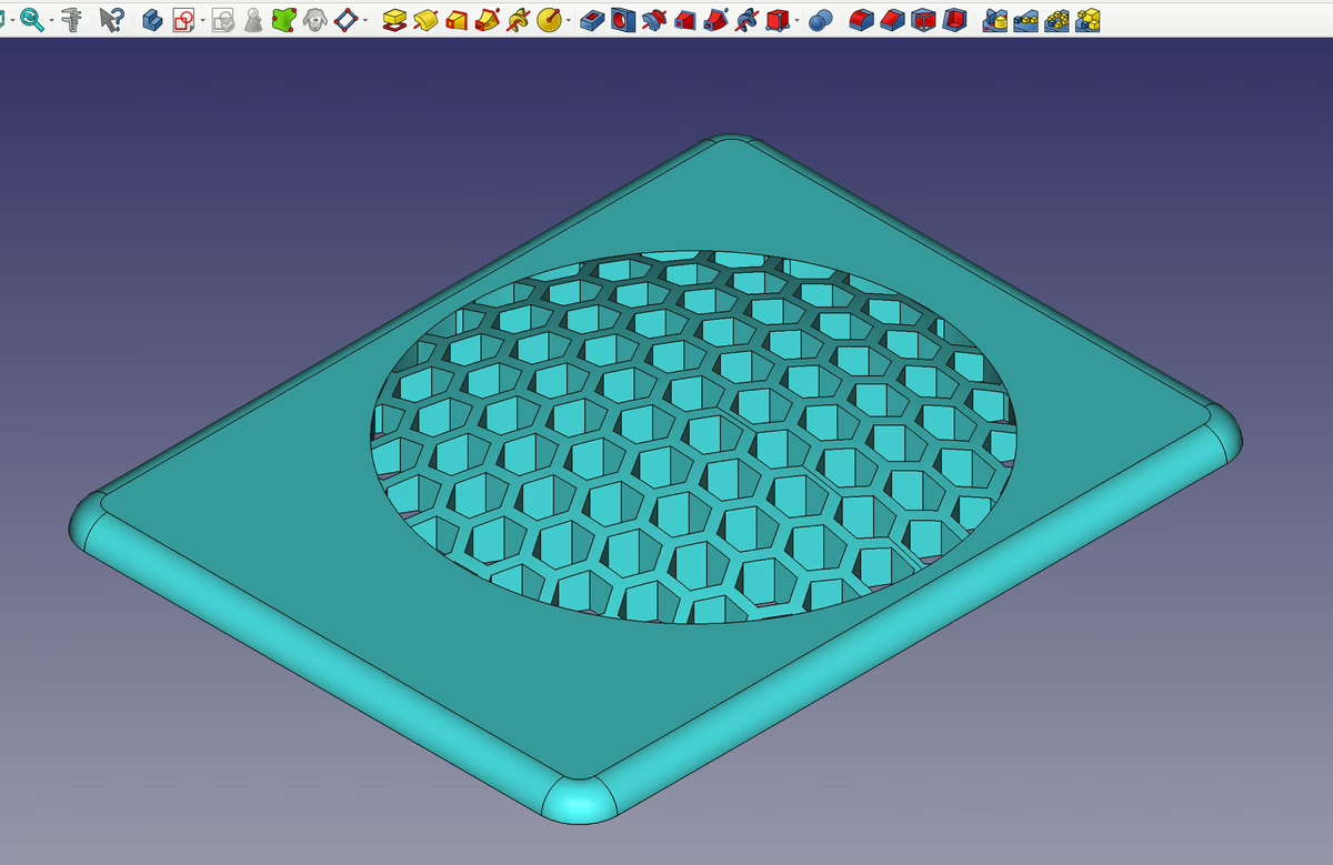
To cool the battery enclosure, I picked up a NF-A6x15 from Noctua that can be powered with 5V. The enclosure will be a 4"x6"x9" cuboid to the left of the automated feeder space - 6" dimension vertically, 9" dimension along front to back of the frame (picture in future post). On the front 4"x6" face, there will be an intake grille; on the back, the fan exhaust and USB ports for power in (charging battery) & out (water pump and feeder).
I've started designing the fan mount/exhaust grille thing in FreeCAD, and spent entirely too long getting the honeycomb part working. I created the honeycomb in a few different ways, but my initial attempts worked poorly with the "cuts" I was trying to make with other solids to get the desired profile. In the end, what worked was modeling exactly two hexagons as separate bodies, unioning them (at the appropriate relative offsets for further tiling), then arraying them along x and along y as independent operations. This gave me a large hexagon "plane", which I cut with a cylinder and then a sphere to create a domed circle look:
Many tears were shed
The dome is 5mm high, and the surrounding surface is 3mm thick, so I had some fun doing the geometry to figure out the correct size of sphere to make the dome cut with.
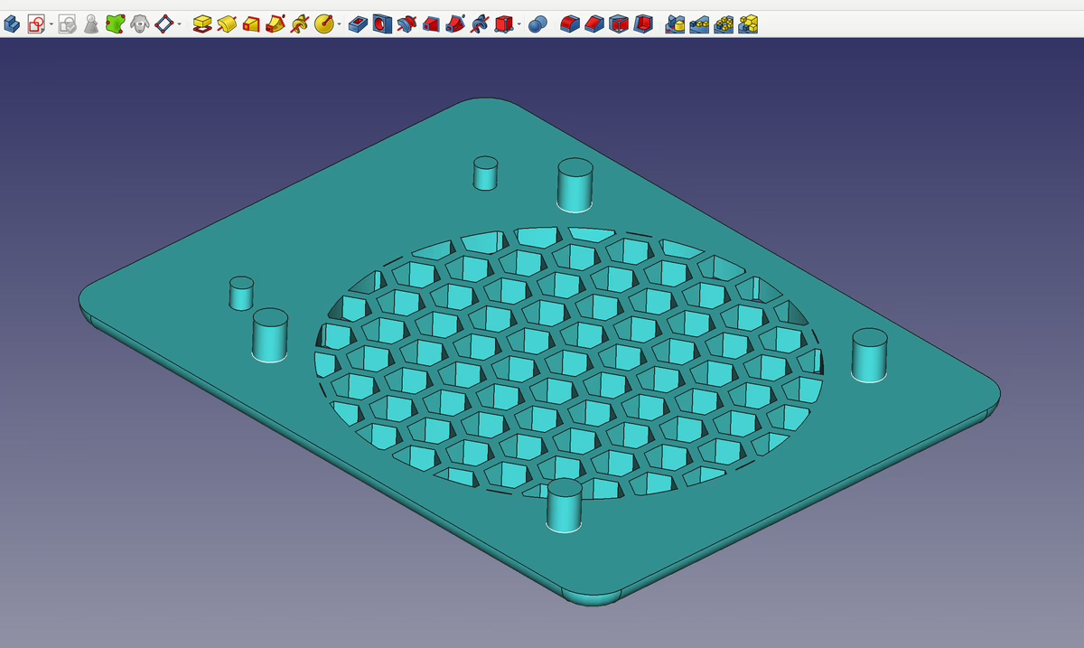
On the other side, we have 4 pegs for locating the fan, and 2 other mystery pegs:
What could those be for?
I lied in my last post when I implied that we only use screws in this house. We use glue too, but only when it makes sense. The USB ports below the fan will be subflush from the 4"x6" back face of the cuboid, to give space for the connector and relax the cable bend requirements. The fan will be flush with the back face. Since a 3D printer is being used to manufacture this, I'll glue the fan grille + USB plate together, instead of printing one big piece with a bunch of wasted support material. The mystery pegs are for registration between the pieces.
The faceplates are sized larger than the holes in the plywood to hide the cut edges, hopefully leaving a nice look. There will be a few more components to this fan grille + USB port assembly; something to hold the fan from the back, and something to attach the assembly to the plywood that it sits in. These won't all get independent features, but I'll post at least 1 photo of the completed assembly.